某网络拓扑结构及参数配置如图6-5所示。其中,(23)的路由表信息如下。 C 192.168.1.0/24 is directly connected,FastEthemet0/0 R 192.168.3.0/241120/1]via 192.168.65.2,00:00:04,Seria12/0 R 192.168.5.0/24[120/2]via 192.168.65.2,00:00:04,Seria12/0 C 192.168.65.0/24 is directlyconnected,Seria12/0 C 192.168.67.0/24 is directly connected,Seria13/0 R 192.168.69.0/24[120/1]via 192.168.65.2,00:00:04,Serial2/0A.路由器R0B.路由器R1C.路由器R2D.计算机PCI
某网络拓扑结构及参数配置如图6-5所示。
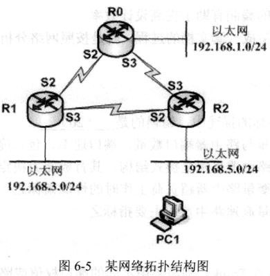
其中,(23)的路由表信息如下。 C 192.168.1.0/24 is directly connected,FastEthemet0/0 R 192.168.3.0/241120/1]via 192.168.65.2,00:00:04,Seria12/0 R 192.168.5.0/24[120/2]via 192.168.65.2,00:00:04,Seria12/0 C 192.168.65.0/24 is directlyconnected,Seria12/0 C 192.168.67.0/24 is directly connected,Seria13/0 R 192.168.69.0/24[120/1]via 192.168.65.2,00:00:04,Serial2/0
A.路由器R0
B.路由器R1
C.路由器R2
D.计算机PCI
相关考题:
若路由器显示的路由信息如下,则最后一行路由信息是____得到的。 R3show ip route Gateway of last resort is not set 192.168.0.0/24 is subnetted,6 subnets C 192.168.1.0 is directly connected,Ethernet0 C 192.168.65.0 is directly connected,Serial0 C 192.168.67.0 is directly connected,Seriall R 192.168.69.0 [120/1] via 192.168.67.2,00:00:15,Seriall [120/1] via 192.168.65.2,00:00:24,Serial0 R 192.168.5.0[120/1] via 192.168.07.2,00:00:15,Seriall R 192.168.3.0[120/1] via 192.168.65.2,00:00:24,Serial0A.串行口直接连接的B.由路由协议发现的C.操作员手工配置的D.以太网端口直连的
某运行RIP协议的校园网拓扑结构图如图7-4所示。在路由器RouterA上定义一条从Internet网到达校园网内部192.168.1.0/24网段的静态路由,完成此任务的配置语句是(56)。A.ip route 192.168.1.0 0.0.0.255 10.0.0.2B.ip route 192.168.1.0 0.0.0.255 S0/1C.ip route 192.168.1.0 255.255.255.0 S0/0D.ip route 192.168.0.0 255.255.255.0 f0/0
某局域网通过两台路由器划分为3个子网,拓扑结构和地址分配如图6-3所示。为路由器R1的e0端口设置一条到达192.168.3.0/24网段的默认路由的配置语句是(49)。A.R1 (config-if) #ip route 0.0.0.0 255.255.255.255 192.168.3.1B.R1 (config-if) #ip route 0.0.0.0 0.0.0.0 192.168.3.1C.R1 (config) #ip route 0.0.0.0 0.0.0.0 192.168.2.2D.R1 (config) #ip route 0.0.0.0 255.255.255.255 192.168.2.2
若路由器显示的路由信息如下,则最后一行路由信息是怎么样得到的?(60) 。R3#show ip routeGateway of last resortis not set192.168.0.0/24 issubnetted, 6 subnetsC 192.168.1.0 isdirectly connected, Ethernet0C 192.168.65.0 isdirectly connected, Serial0C 192.168.67.0 isdirectly connected, SeriallR 192.168.69.0 [120/1]via 192.168.67.2,00:00:15, Seriall[120/1]via 192.168.65.2,00:00:24, Serial0R 192.168.5.0[120/1] via192.168.07.2,00:00:15,SeriallR 192.168.3.0[120/1] via 192.168.65.2,00:00:24Serial0A.串行口直接连接的B.由路由协议发现的C.操作员手工配置的D.以太网端口直连的
● 网络配置如下图所示:其中某设备路由表信息如下:C 192.168.1.0/24 is directly connected, FastEthernet0/0R 192.168.3.0/24 [120/1] via 192.168.65.2, 00:00:04, Serial2/0R 192.168.5.0/24 [120/2] via 192.168.65.2, 00:00:04, Serial2/0C 192.168.65.0/24 is directly connected, Serial2/0C 192.168.67.0/24 is directly connected, Serial3/0R 192.168.69.0/24 [120/1] via 192.168.65.2, 00:00:04, Serial2/0则该设备为 (28) ,从该设备到PC1经历的路径为 (29) 。路由器R2接可能的IP 地址为 (30) 。(28)A. 路由器R0B. 路由器R1C. 路由器R2D. 计算机PC1(29)A. R0→R2→PC1B. R0→R1→R2→PC1C. R1→R0→PC1D. R2→PC1(30)A. 192.168.69.2B. 192.168.65.2C. 192.168.67.2D. 192.168.5.2
●若路由器显示的路由信息如下,则最后一行路由信息是怎么样得到的?(60) 。R3#show ip routeGateway of last resort is not set192.168.0.0/24 is subnetted, 6 subnetsC 192.168.1.0 is directly connected, Ethernet0C 192.168.65.0 is directly connected, Serial0C 192.168.67.0 is directly connected, SeriallR 192.168.69.0 [120/1] via 192.168.67.2,00:00:15, Seriall[120/1] via 192.168.65.2,00:00:24, Serial0R 192.168.5.0[120/1] via 192.168.07.2,00:00:15,SeriallR 192.168.3.0[120/1] via 192.168.65.2,00:00:24 Serial0(60)A.串行口直接连接的B.由路由协议发现的C.操作员手工配置的D.以太网端口直连的
网络配置如下图所示:其中某设备路由表信息如下:C 192.168.1.0/24 is directly connected,FastEthemet0/0R 192.168.3.0/24[120/1]via 192.168.65.2,00:00:04,Serial2/0R 192.168.5.0/24[120/2]via 192.168.65.2,00:00:04,Serial2/0C 192.168.65.0/24 is directly connected,Sefial2/OC 192.168.67.0/24 is directly connected,Serial3/0R 192.168.69.0/24 1 120/1]via 192.168.65.2,00:OO:04,SeriM2/0则该设备为( ),从该设备到PCI经历的路径为( )。路由器R2接口s2可能的IP地址为( )。A.路由器R0B.路由器R1C.路由器R2D.计算机PCI
在某路由器上查看路由信息,结果如下所示。其中表示“S”表明这条路由是__(28)__。 192.168.0.0/24 is subnetted,1 subnets S 192.168.1.0[1/0] via 10.1.1.1 10.0.0.0/24 is subnetted,1 subnets C 10.1.1.0 is directly connected,Ethernet0A.源路由B.静态路由C.发送路由D.快捷路由
某单位网络结构如图1-1所示,网络中所有路由器均使用RIP协议。图1-1在网络部署完成后进行如下测试:1.在主机host101上对Router2的F0/0口及网络1的host1进行了连通性测试,结果如图1-2和图1-3所示。host101ping 192.168.0.1Pinging 192.168.0.1 with 32 bytes of data:Reply from 192.168.0.1: bytes=32 time=1ms TTL=64Reply from 192.168.0.1: bytes=32 time=1ms TTL=64Reply from 192.168.0.1: bytes=32 time=1ms TTL=64Reply from 192.168.0.1: bytes=32 time=1ms TTL=64Ping statistics for 192.168.0.1:Packets: Sent = 4,Received = 4,Lost = 0 (0% loss),Approximate round trip times in milli-seconds:Minimum = 1ms,Maximum = 1ms,Average = 1ms图1-2host101ping 192.168.0.2Pinging 192.168.0.2 with 32 bytes of data:Request timed out.Request timed out.Request timed out.Request timed out.Ping statistics for 192.168.0.2:Packets: Sent = 4, Received = 0, Lost = 4 (100% loss),图1-32.在主机host3上对网络1进行了连通性测试,结果如图1-4所示。host13ping 192.168.0.2Pinging 192.168.0.1 with 32 bytes of data:Reply from 192.168.0.1: bytes=32 time=1ms TTL=64Reply from 192.168.0.1: bytes=32 time=1ms TTL=64Reply from 192.168.0.1: bytes=32 time=1ms TTL=64Reply from 192.168.0.1: bytes=32 time=1ms TTL=64Ping statistics for 192.168.0.1:Packets: Sent = 4,Received = 4,Lost = 0 (0% loss),Approximate round trip times in milli-seconds:Minimum = 1ms,Maximum = 1ms,Average = 1ms图1-43.查看路由器Router3的路由表,结果如图1-5所示。Router3show ip routeR 192.168.0.0/24 [120/1] via 202.117.112.1, 00:00:24,Serial2/0C 192.168.1.0/24 is directly connected,FastEthemet0/0R 192.168.2.0/24 [120/1] via 202.117.114.1,00:00:01,Serial3/0202.117.112.0/30 is subnetted,1 subnetsC 202.117.112.0 is directly connected,Serial2/0R 202.117.113.0/30 [120/1] via 202.117.112.1,00:00:24,Serial2/0[120/1] via 202.117.114.1,00:00:01,Serial3/0202.117.114.0/30 is subnetted,1 subnetsC 202.117.114.0 is directly connected,Serial3/0图1-5【问题1】(6分)请填写hostl的Internet协议属性参数。IP地址: (1)子网掩码: (2)默认网关: (3)
某单位通过2Mbps的DDN专线接入广域网,网络拓扑结构如图6-5所示。该单位申请的公网IP地址为61.246.100.96/29。其中,该单位能够使用的有效公网地址有(70)个。A.5B.6C.7D.8
在本地路由表如下所示,路由器把目标地址为10.1.5.65的分组发送给( )。Network Interface Next-hop 10.1.1.0/24 e0 Directly connected 10.1.2.0/24 e1 Directly connected 10.1.5.0/24 s1 10.1.1.2 10.1.5.64/28 e0 10.1.2.2 10.1.5.64/29 s0 10.1.3.3 10.1.5.64/27 s1 10.1.4.4A.10.1.1.2 B.10.1.2. 2 C.10.1.3. 3 D.10.1.4. 4
某网络拓扑结构如下:在路由器R2上采用show ip rout命令得到如下所示结果。 R2 ... R 192.168.2.0/24[120/1] via 61.114.112.1,00:00:11,Serial2/0 C 192.168.1.0/24 is directly connected,FastEthernet0/0 61.114.112.0/30 is subnetted,1 subnets C 61.114.112.0 is directly connected,Serial2/0 R2 则host1可能的IP地址为( ),路由器R1的S2/0口的IP地址为( )。A.192.168.2.1B.192.168.1.1C.61.114.112.1D.61.114.112.2A.192.168.2.1B.192.168.1.1C.61.114.112.1D.61.114.112.2
某网络拓扑结构如下:在路由器R2上采用show ip rout命令得到如下所示结果。R2>..R 192.168.2.0/24[120/1] via 61.114.112.1,00:00:1l,Seria12/0C 192.168.1.0/24 is directly connected,FastEthernet0/061.114.112.0/30 is subnetted,1 subnetsC 61.114.112.0 is directly cormected,Seria12/0R2>则hostl可能的IP地址为( ),路由器R1的S2/0口的IP地址为(请作答此空)。A.192.168.2.1B.192.168.1.1C.61.114.112.1D.61.114.112.2
某网络拓扑结构如下图所示。在路由器R2上采用命令 ( ) 得到如下图所示结果。PC1可能的IP地址为 ( ) ,路由器R2的S0口的IP地址为 ( ) ,若PC1上查看主机的路由表,采用命令为 (本题) 。R2> ... R 192.168.0.0/24[120/1] via 202.117.112.1, 00:00:11, Serial2/0 C 192.168.1.0/24 is directly connected, FastEthernet0/0 .117.112.0/30 is subnetted,1subnets C 202.117.112.0 is directly connected, Seria12/0 R2>A.nslookupB.route printC.ip routingD.show ip route
某单位的拓扑图如下图所示:路由器AR2路由表内容如下所示。从路由信息中可以看出,pcl所在网段是();A.192.168.0.0/24B.192.168.1.0/24C.201.1.1.0/30D.127.0.0.0/24
阅读以下说明,回答问题1和问题2,将解答填入答题纸对应的解答栏内。【说明】某公司有3个分支机构,网络拓扑结构及地址分配如图4-1所示。【问题1】(每空1分,共11分)公司申请到202.111.1.0/29的公有地址段,采用NAPT技术实现公司内部访问互联网的要求,其中,192.168.16.0/22网段禁止访问互联网。 R1、R2和R3的基本配置已正确配置完成,其中R1的配置如下。请根据拓扑结构,完成下列配置代码。
网络配置如下图所示: 其中某设备路由表信息如下: Route Flags: R - relay, D - download to fib------------------------------------------------------------------------------Routing Tables: Public Destinations : 6 Routes : 6 Destination/Mask Proto Pre Cost Flags NextHop Interface192.168.1.0/24 Direct 0 0 D 127.0.0.1 FastEthernet0/0192.168.3.0/24 RIP 100 1 D 192.168.65.2 Serial2/0192.168.5.0/24 RIP 100 2 D 192.168.65.2 Serial2/0192.168.65.0 Direct 0 0 D 127.0.0.1 Serial2/0192.168.67.0/24 Direct 0 0 D 127.0.0.1 Serial3/0192.168.69.0/24 RIP 100 1 D 192.168.65.2 Serial2/0则该设备为 ( ) ,从该设备到PC1经历的路径为 ( ) 。路由器R2接口S2可能的IP地址为 ( 在此空作答) 。A.192.168.69.2B.192.168.65.2C.192.168.67.2D.192.168.5.2
某网络拓朴结构如下图所示。 在路由器 R2 上得到如下所示结果。 R2> R 192.168.0.0/24[120/1] via 202.117.112.1, 00:00:11, Serial 2/0 C 192.168.1.0/24 is directly connected, FastEthernet 0/0 202.117.112.0/30 is subnetted, 1 subnets C 202.117.112.0 is directly connected, Serial 2/0则 PC1 可能的 IP 地址为( )。A.192.168.0.1 B.192.168.1.1 C.202.117.112.1D.202.117.112.2
网络配置如下图所示:其中某设备路由表信息如下: Route Flags: R - relay, D - download to fib------------------------------------------------------------------------------Routing Tables: Public Destinations : 6 Routes : 6 Destination/Mask Proto Pre Cost Flags NextHop Interface192.168.1.0/24 Direct 0 0 D 127.0.0.1 FastEthernet0/0192.168.3.0/24 RIP 100 1 D 192.168.65.2 Serial2/0192.168.5.0/24 RIP 100 2 D 192.168.65.2 Serial2/0192.168.65.0 Direct 0 0 D 127.0.0.1 Serial2/0192.168.67.0/24 Direct 0 0 D 127.0.0.1 Serial3/0192.168.69.0/24 RIP 100 1 D 192.168.65.2 Serial2/0则该设备为 ( ) ,从该设备到PC1经历的路径为 (在此空作答) 。路由器R2接口S2可能的IP地址为 ( ) 。A.R0→R2→PC1B.R0→R1→R2→PC1C.R1→R0→PC1D.R2→PC1
某网络拓扑结构如下图所示。在路由器R2上采用命令 ( ) 得到如下图所示结果。PC1可能的IP地址为 (本题) ,路由器R2的S0口的IP地址为 ( ) ,若PC1上查看主机的路由表,采用命令为 ( ) 。R2> ... R 192.168.0.0/24[120/1] via 202.117.112.1, 00:00:11, Serial2/0 C 192.168.1.0/24 is directly connected, FastEthernet0/0 .117.112.0/30 is subnetted,1subnets C 202.117.112.0 is directly connected, Seria12/0 R2>A.192.168.0.1B.192.168.1.1C.202.117.112.1D.202.117.112.2
某网络拓扑结构如下图所示。在路由器R2上采用命令 (本题) 得到如下图所示结果。PC1可能的IP地址为 ( ) ,路由器R2的S0口的IP地址为 ( ) ,若PC1上查看主机的路由表,采用命令为 ( ) 。R2> ... R 192.168.0.0/24[120/1] via 202.117.112.1, 00:00:11, Serial2/0 C 192.168.1.0/24 is directly connected, FastEthernet0/A.nslookupB.route printC.ip routingD.show ip route
某单位拓扑图如下图所示:路由器AR2路由表内容如下所示.从路由信息中可以看出,DHCPServer所在网段是()A.192.168.0.0/24B.192.168.1.0/24C.201.1.1.0/30D.127.0.0.0/24
某网络拓扑结构如下图所示。在路由器R2上采用命令 ( ) 得到如下图所示结果。PC1可能的IP地址为 ( ) ,路由器R2的S0口的IP地址为 (本题) ,若PC1上查看主机的路由表,采用命令为 ( ) 。R2> ... R 192.168.0.0/24[120/1] via 202.117.112.1, 00:00:11, Serial2/0 C 192.168.1.0/24 is directly connected, FastEthernet0/0 A.192.168.0.1B.192.168.1.1C.202.117.112.1D.202.117.112.2
网络配置如下图所示: 其中某设备路由表信息如下: Route Flags: R - relay, D - download to fib------------------------------------------------------------------------------Routing Tables: Public Destinations : 6 Routes : 6 Destination/Mask Proto Pre Cost Flags NextHop Interface192.168.1.0/24 Direct 0 0 D 127.0.0.1 FastEthernet0/0192.168.3.0/24 RIP 100 1 D 192.168.65.2 Serial2/0192.168.5.0/24 RIP 100 2 D 192.168.65.2 Serial2/0192.168.65.0 Direct 0 0 D 127.0.0.1 Serial2/0192.168.67.0/24 Direct 0 0 D 127.0.0.1 Serial3/0192.168.69.0/24 RIP 100 1 D 192.168.65.2 Serial2/0则该设备为 (在此空作答) ,从该设备到PC1经历的路径为 ( ) 。路由器R2接口S2可能的IP地址为 ( ) 。A.路由器R0B.路由器R1C.路由器R2D.计算机PC1
某网络拓扑如下图所示。要得到如下所示的输出信息,应在设备()上执行()命令。A.R1B.R2C.R3D.R4